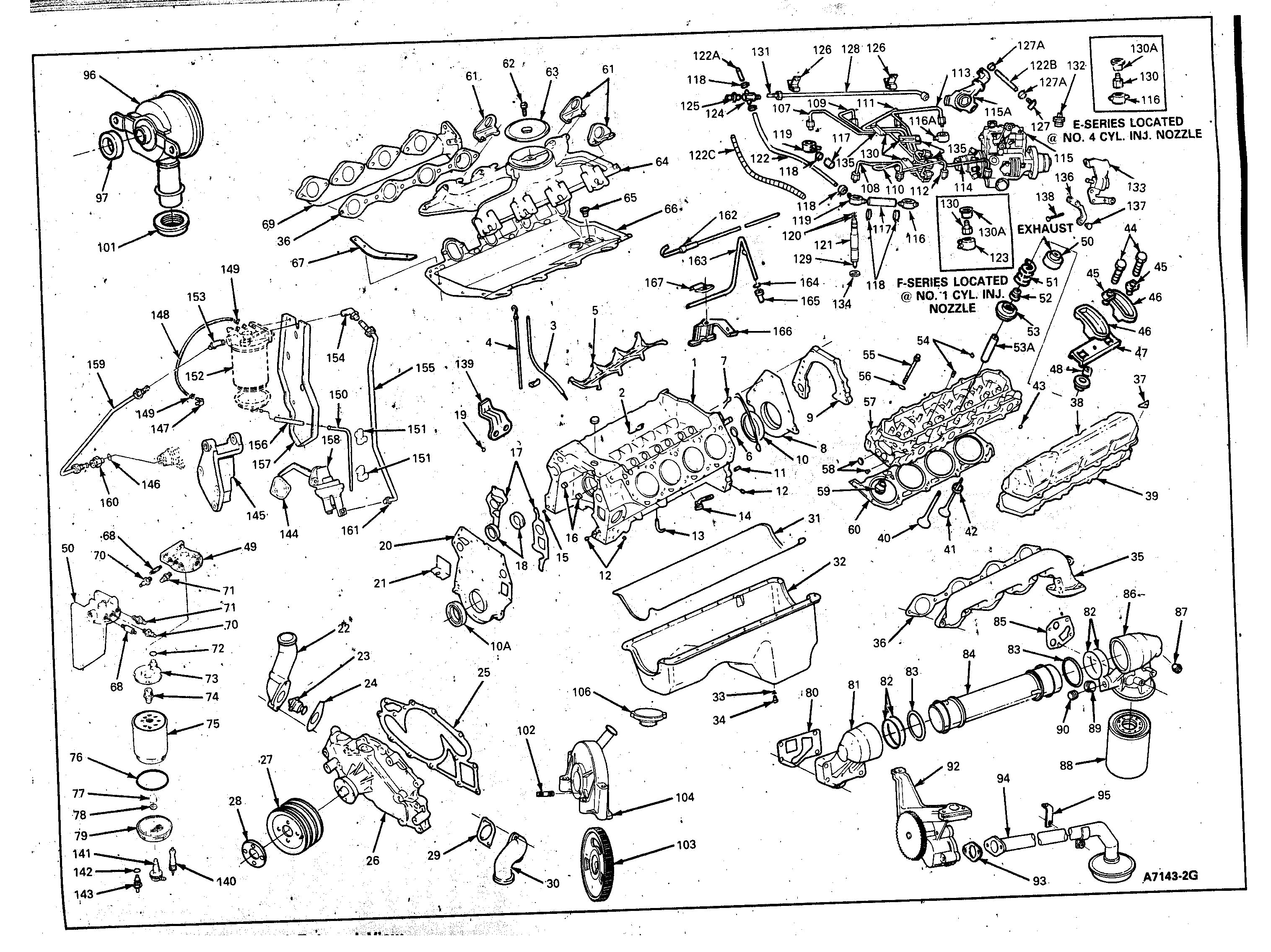
Skoda Engine Diagram
- Category : Engine Diagram
- Post Date : January 22, 2026
Skoda Engine Diagram
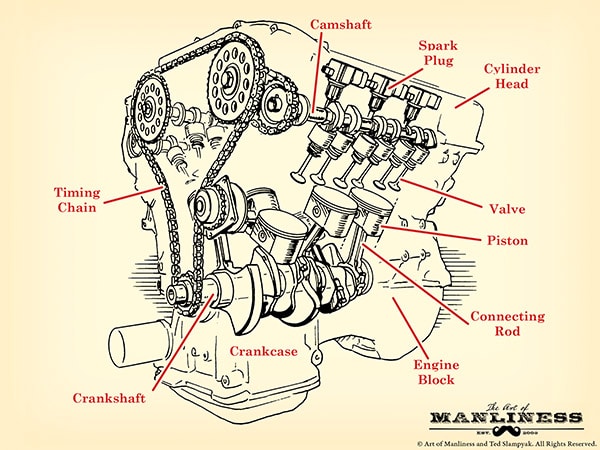
How A Car Engine Works
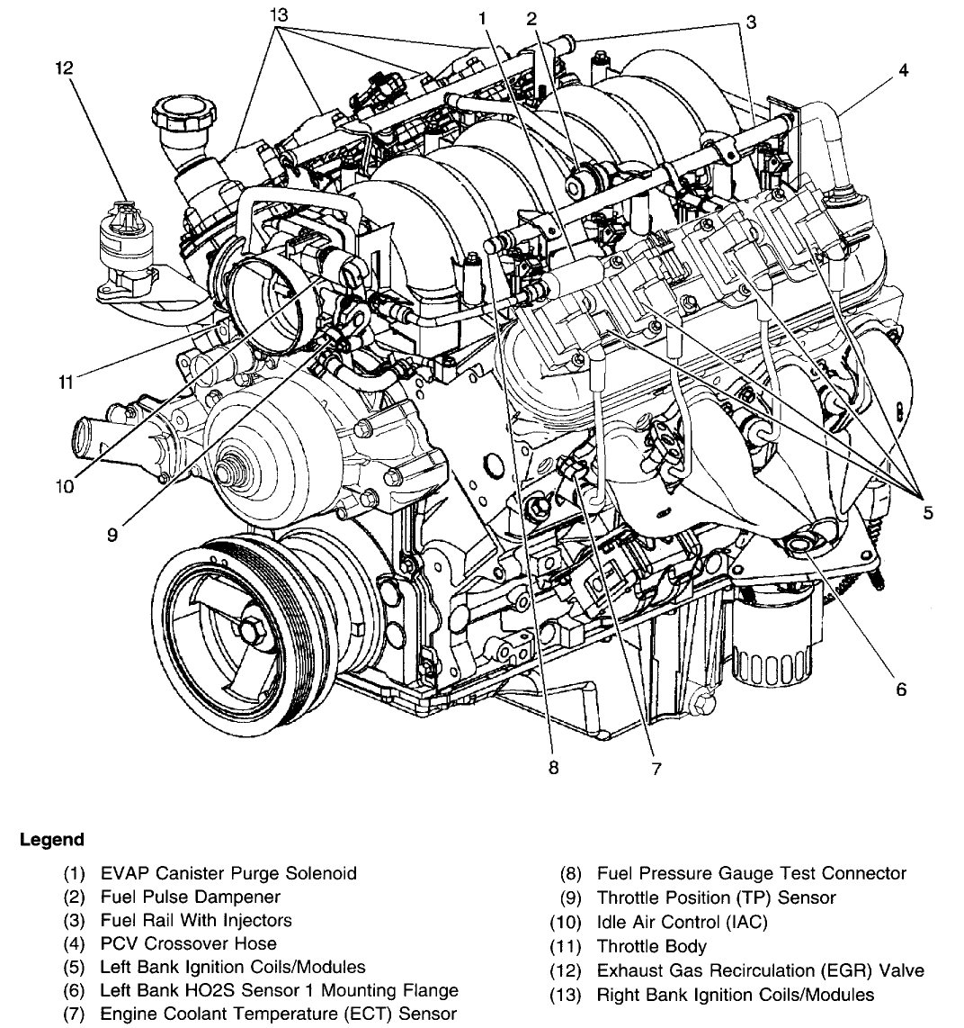
Engine Diagrams - Ls1tech

Morgan Motors
Engine Diagrams - Ls1tech
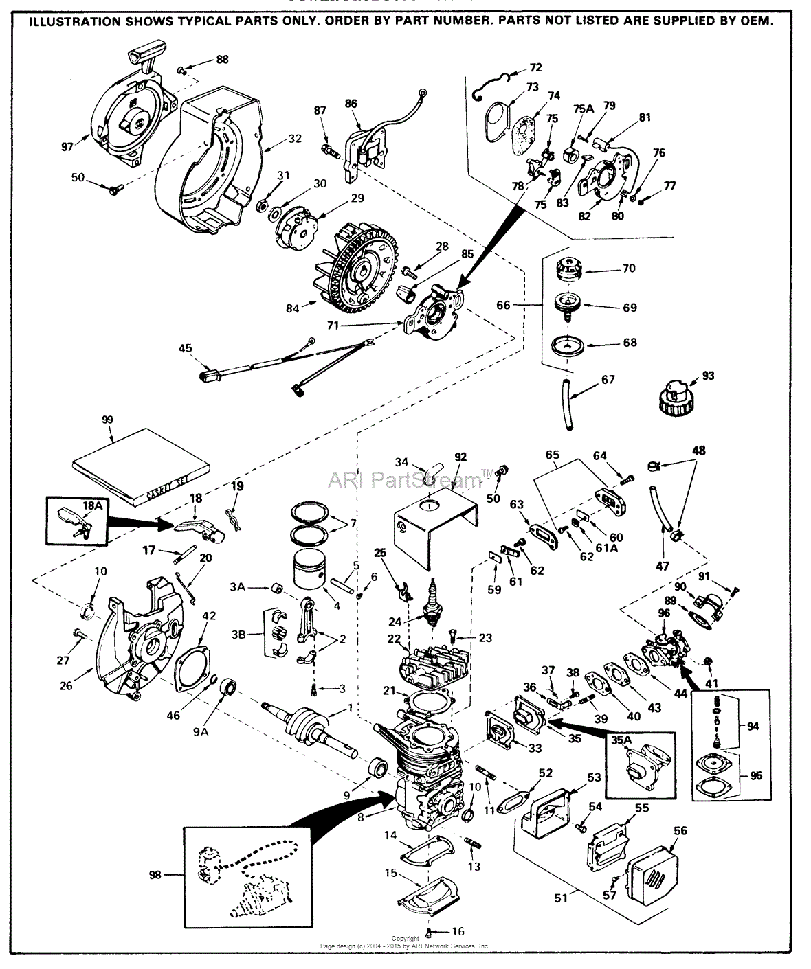
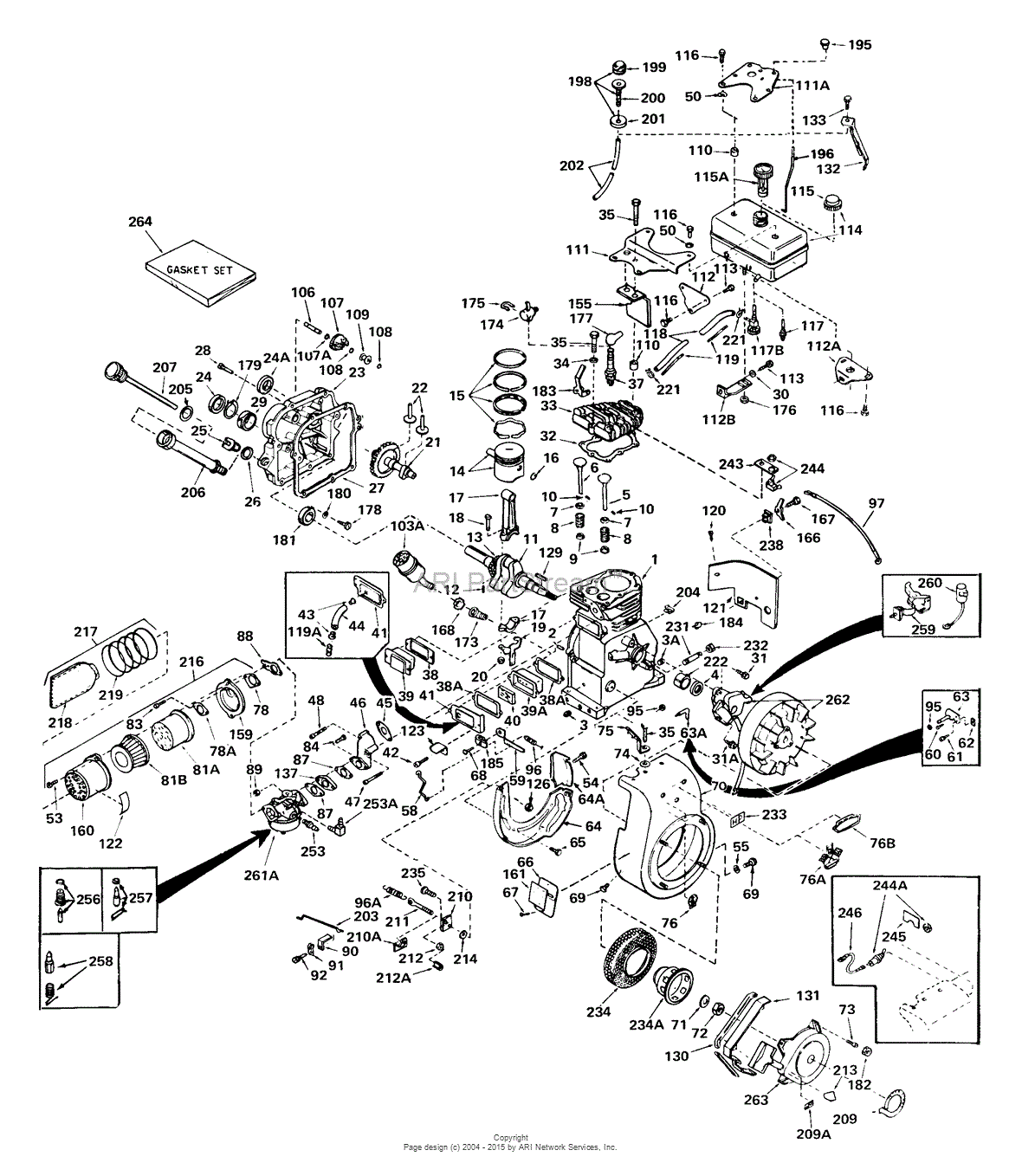
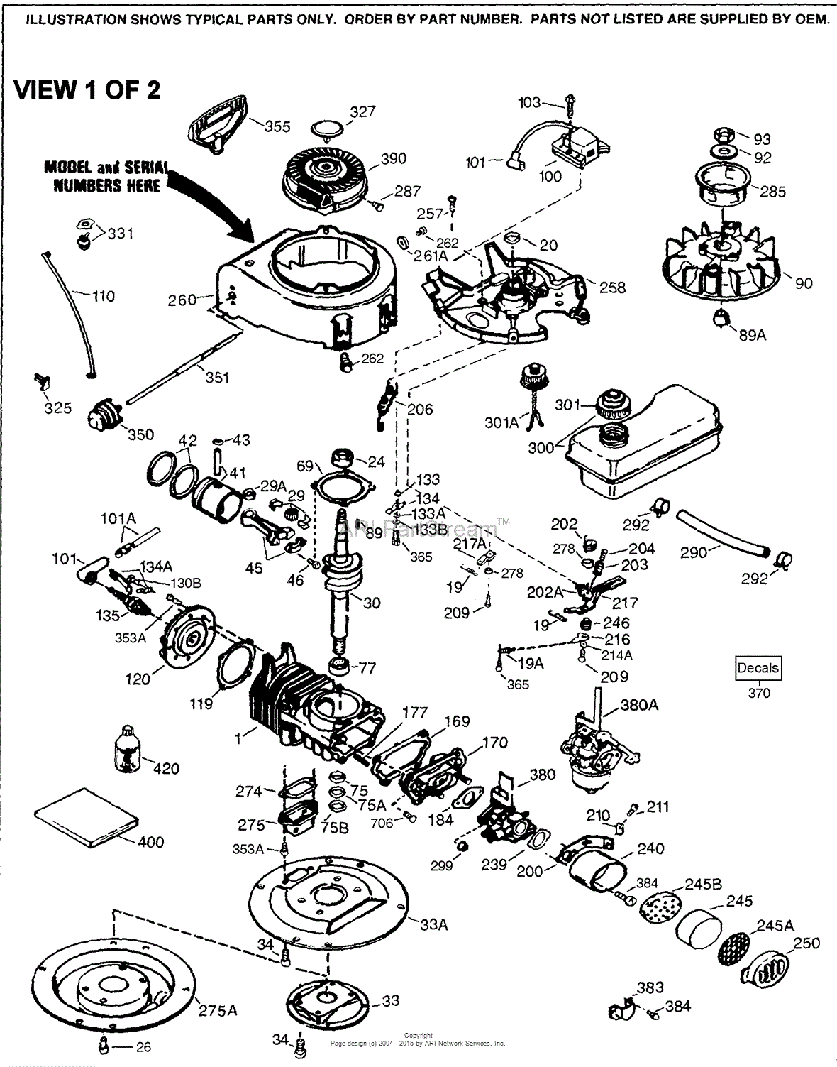
Tecumseh Ah520

Omrg33363 8 1 L 6081hfn04 Natural Gas Engines Block File
Engine And Jet Drive
Tomographymeetsmasochism February 2011
Engine Diagrams - Ls1tech

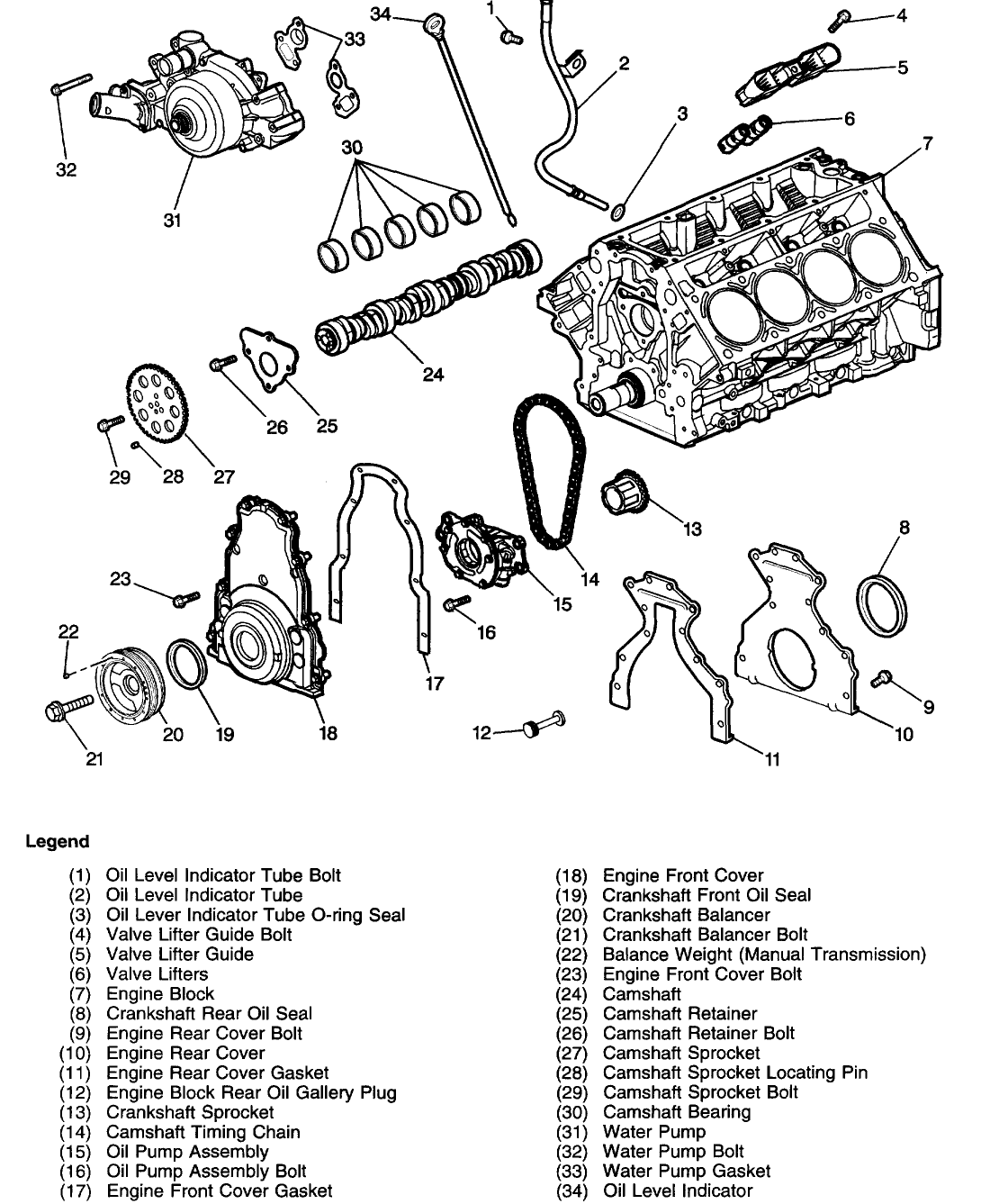
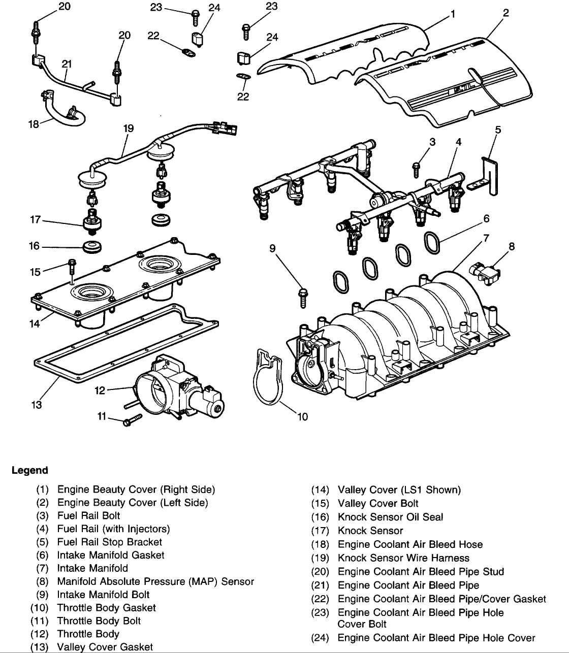
Complete V

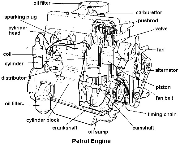
Basic Car Engine Parts Diagram
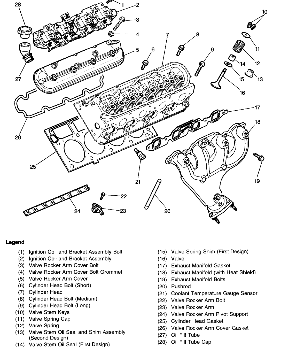
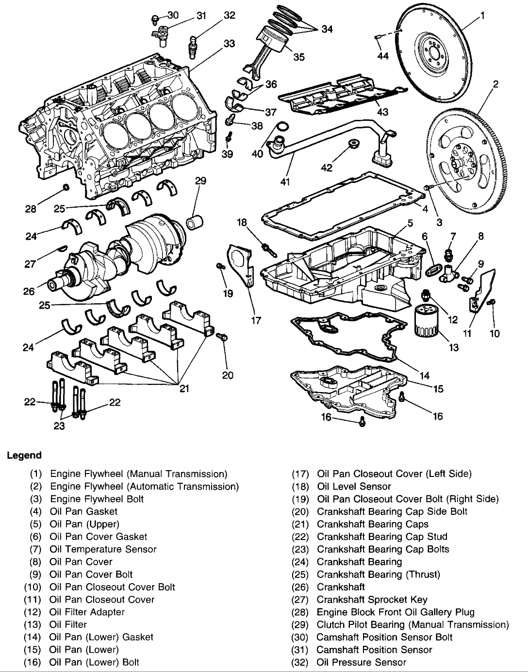
Engine Diagrams
Oil Pump Location And Replacement

Saturn V F
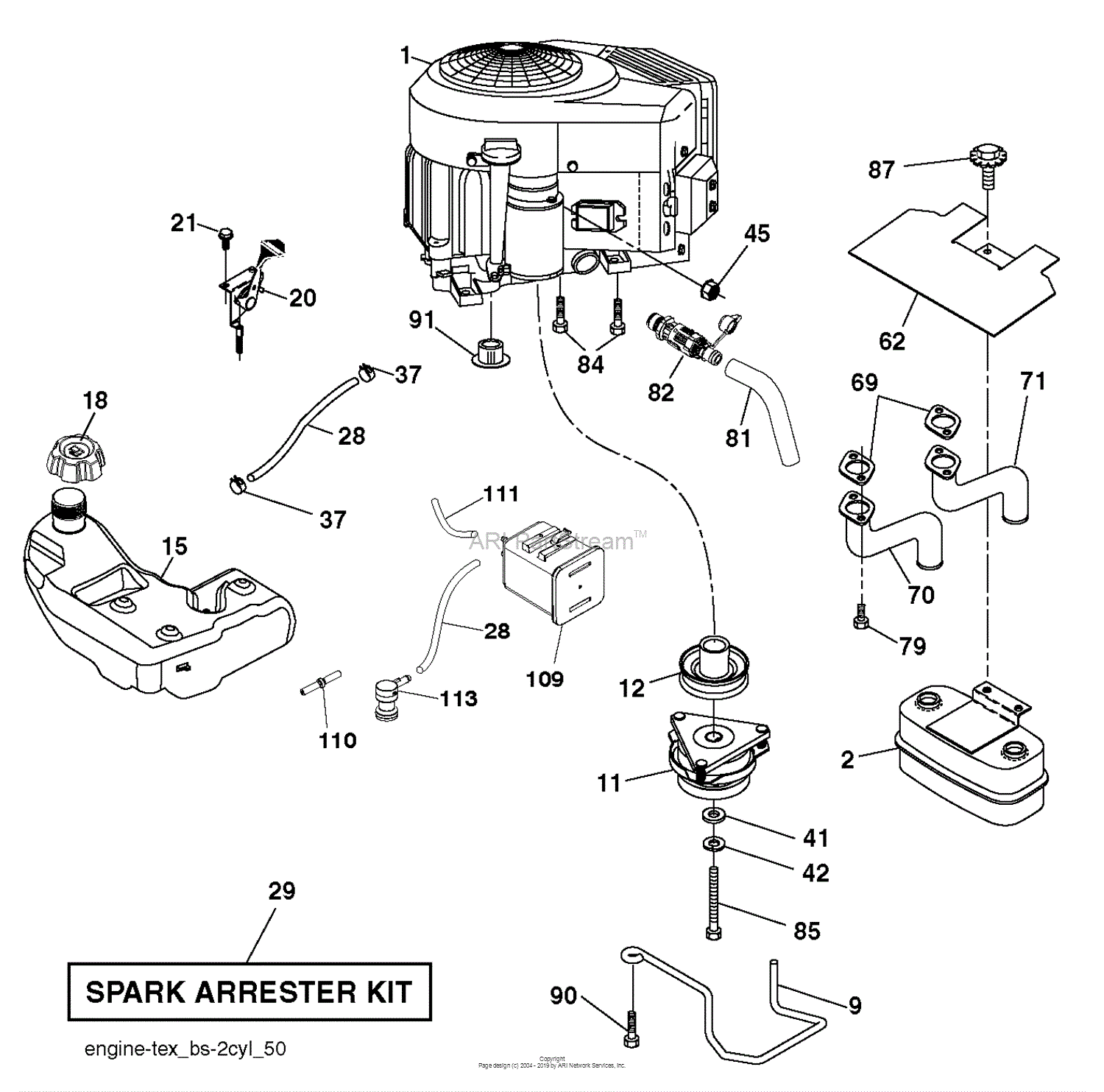
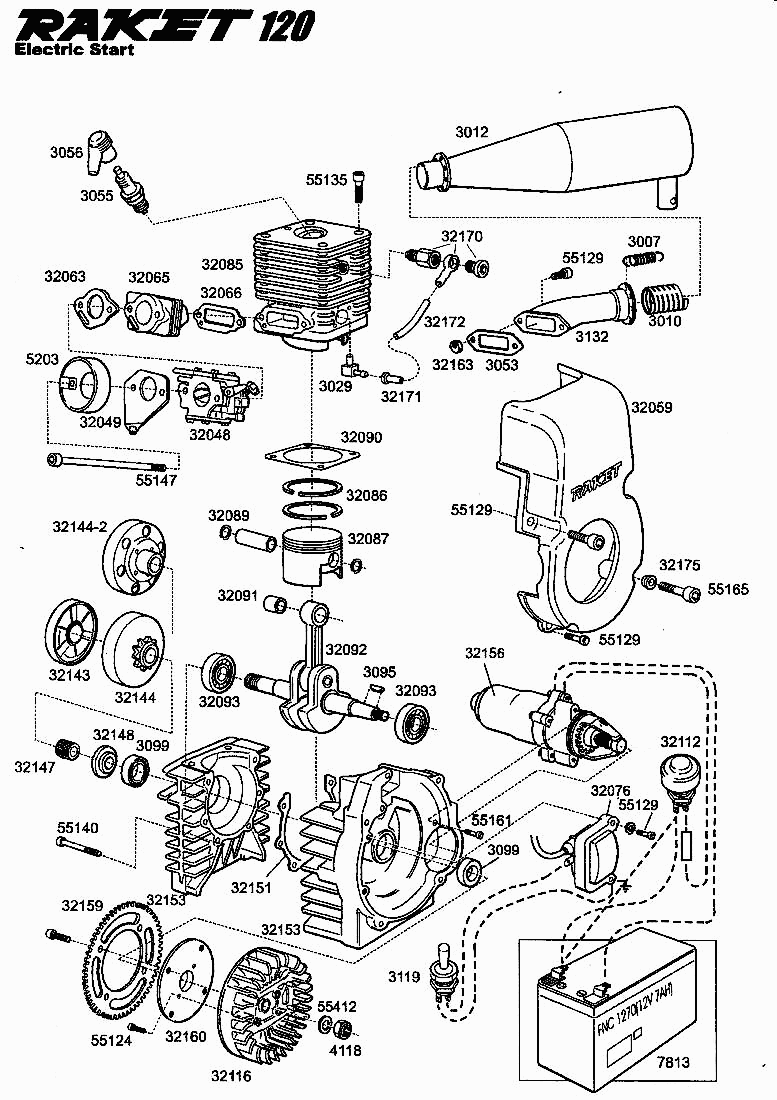
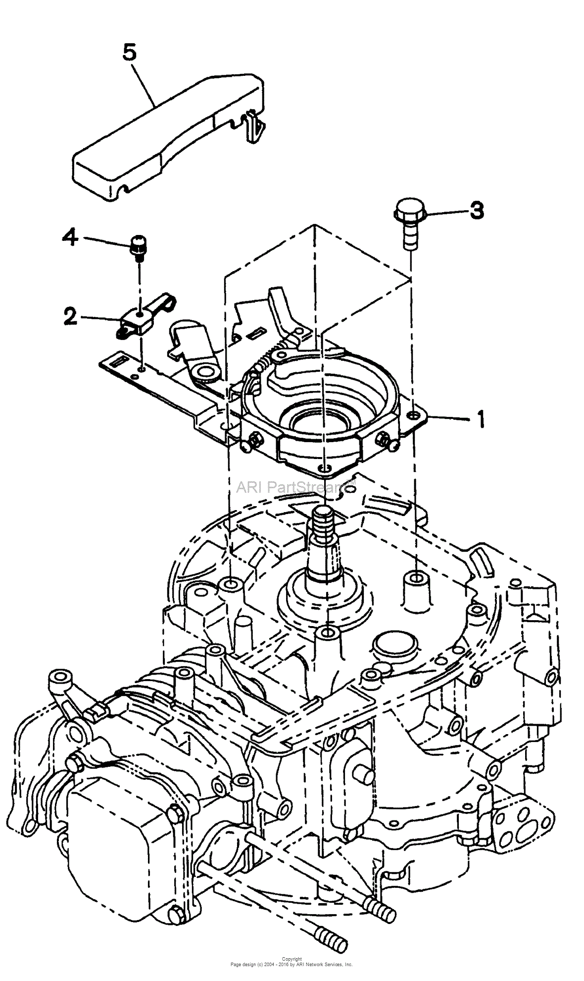
Husqvarna Yth24v48

File Single
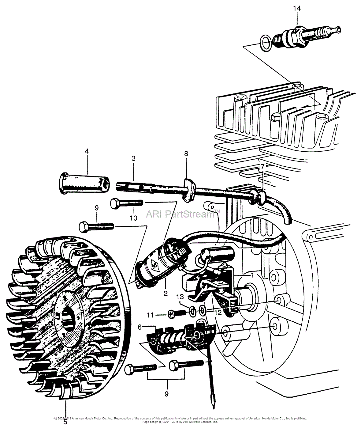
Honda Engines G30 A Engine Jpn Vin G30
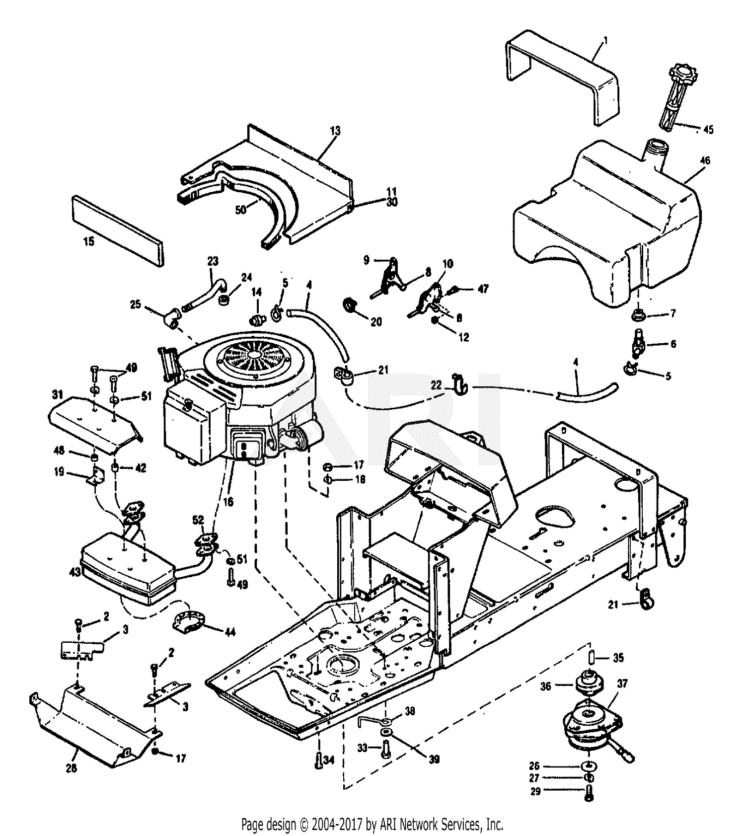
Troy Bilt 13065 14hp Hydro Suburban Tractor S N
Engine And Jet Drive
What Are The Basic Parts Of An Engine
Robin Subaru Ex21 Parts Diagram For Crankcase
Mtd 216
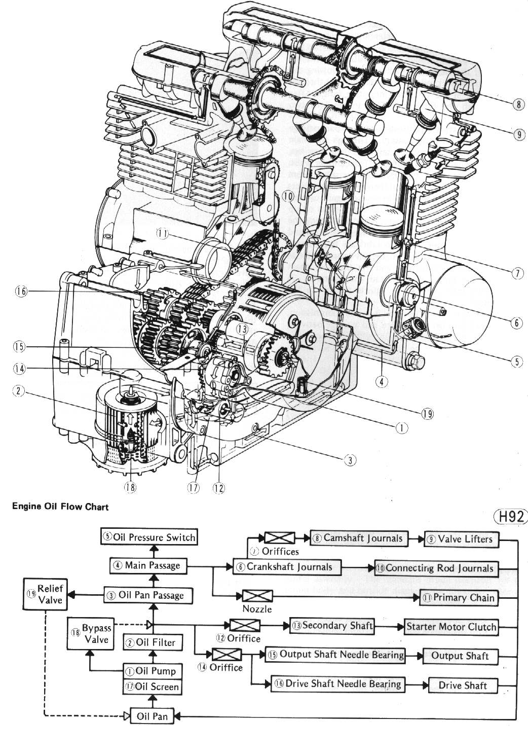
Dan U0026 39 S Motorcycle Four Stroke Oil Flow

Diagrams For U0026 39 96-99 - Page 3
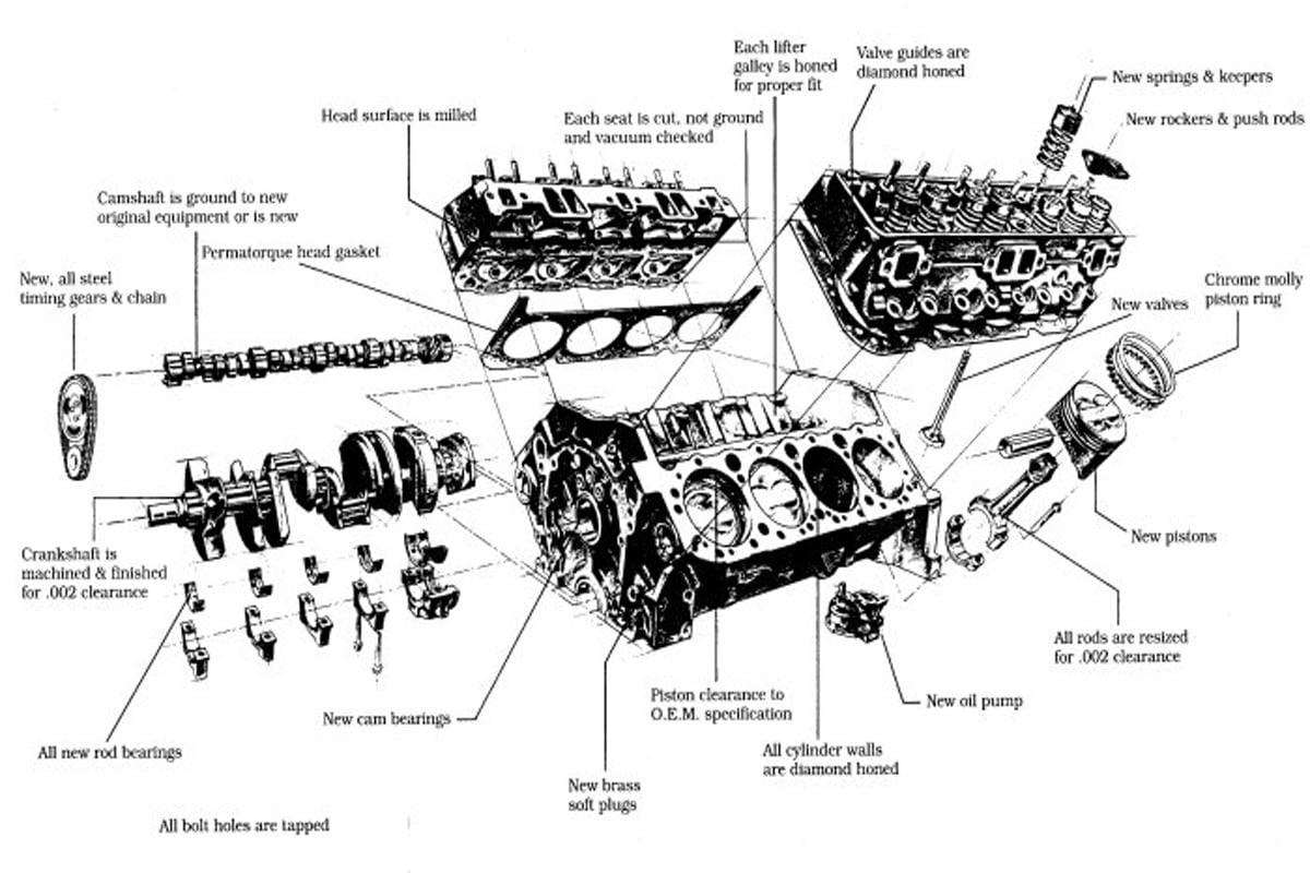
Small Block 265 283 307 305 327 350 400
Generac 0972

1938 Wolseley 14 60 V8 Street Rod Build July 2010
Husqvarna Yt48cs
Tecumseh Hm70
Snapper Eh18v 6 5 Hp 4 Cycle Ohv Robin Engine Parts
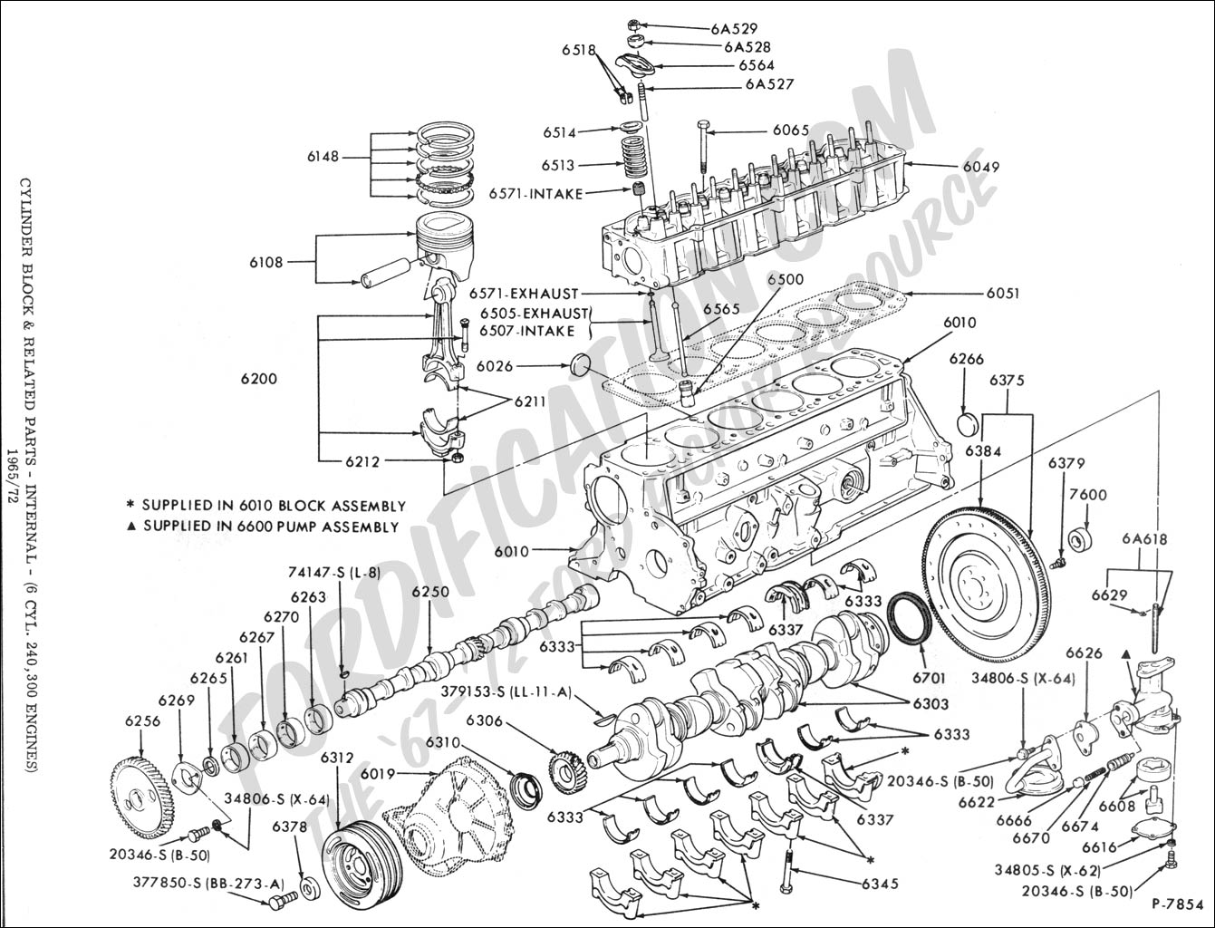
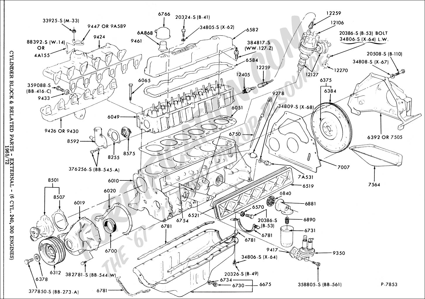
Ford Truck Technical Drawings And Schematics

The Stuart Turner P5 Marine Engine

British Auto Parts Ltd

Repair Guides
Tecumseh H22

Automotive Engine Compartment Parts And Connection Diagram
Eap Vocabulary Dealing With Meaning
Ls3 Powered Ak Cobra Gen Iii Build 16 Engine N Trans

We Need A Parts Diagram For Our 1988 Ford Tempo Gl There
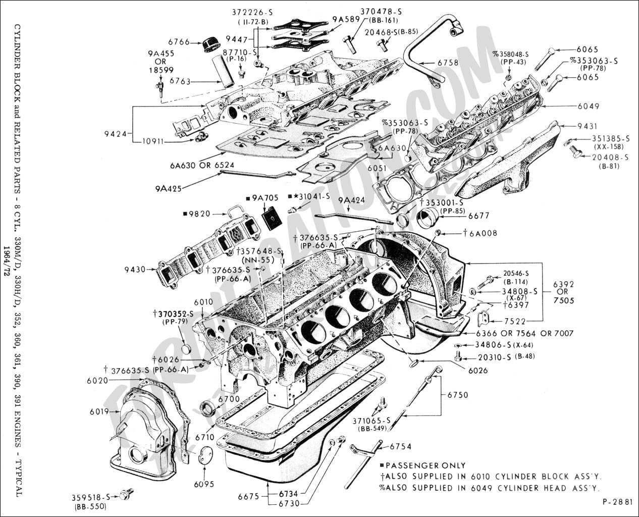
Ford Truck Technical Drawings And Schematics
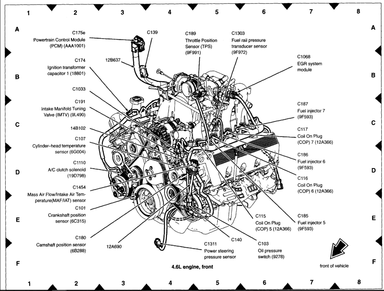
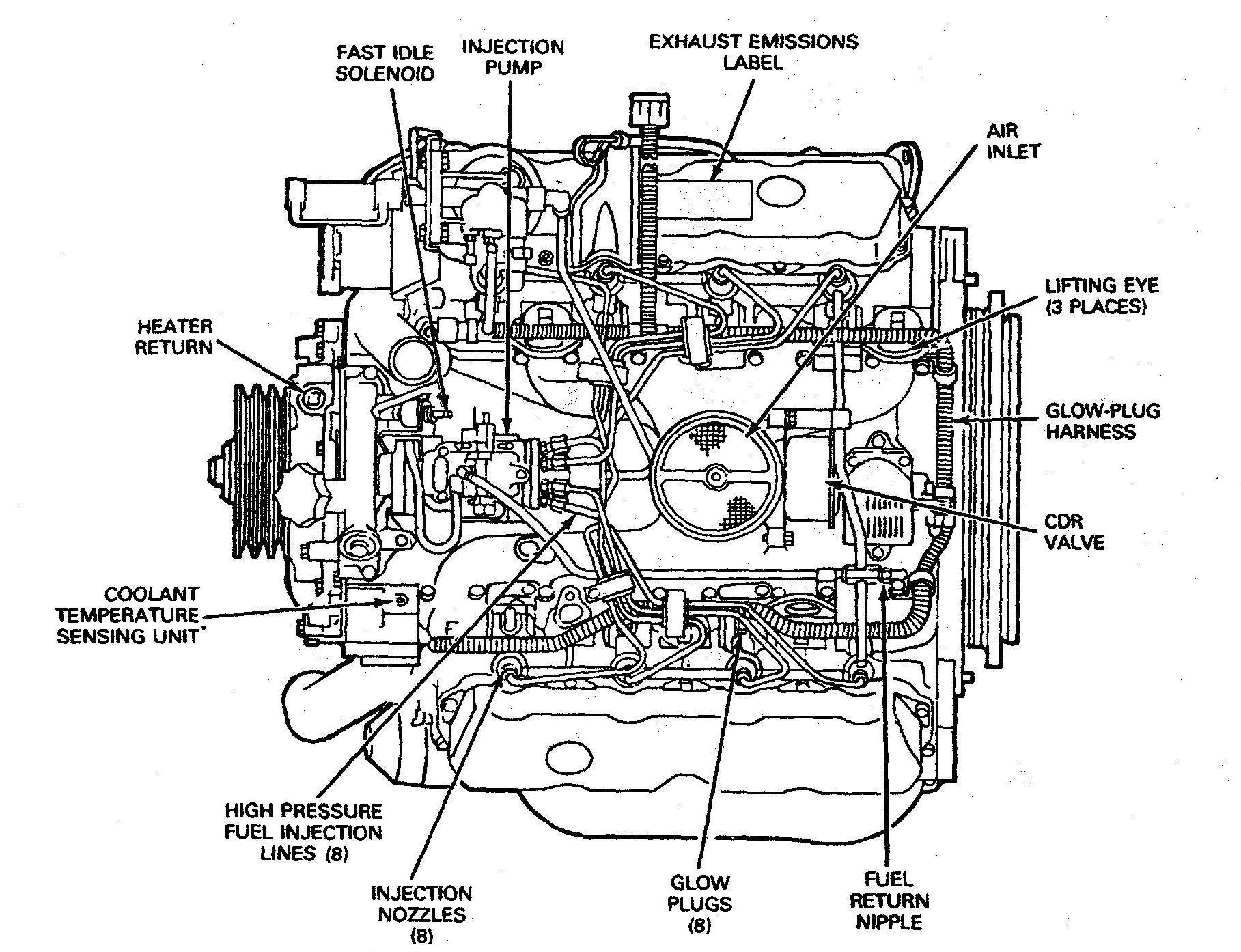
Location Of The Coolant Temperature Sensor Engine

Computerized Engine Controls
Tecumseh Av520
Items Similar To A Modern Internal Combustion Engine

Heres Some Diagrams For People With 5 4l U0026 39 S

Possible Ford Mustang Gt500 Engine Drawings Leak

Marine Diesel Engines U2013 Parts Fuel Lubrication Cooling
How Diesel Engines Work - Part

Ford Vulcan Engine

History Of The Ls Engine And Cylinder Head Casting Number


Mechanical Engineering Toyota Engine Exploded View

Cb750 Sohc Diagrams For Engine Parts Diagram
Snapper Ec13v 4 Hp 2 Cycle Robin Engine Parts Diagram For
Diagram Skoda Engine Diagram
Download Skoda Engine Diagram
I'm posting here a simple project to create an interrupt timer on an ESP32 board for version 3.1.1 by Esspressif Systems. I had difficulties to find updated information to make this code, I hope it can be useful to someone ! This code creates an interrupt every 100ms and counts the number of interrupts. There is the code : #include "esp32 hal timer.h" const int ledPin = 2; pin of the LED ...
Watchdog timer WDT prevent esp32 from stucking Projects Programming arpa123 October 4, 2024, 3:27pm
As you understand I need a hardware timer (counting clock ticks). Millis () makes demanding to ckeck if "old value" is smaller than millis () value (normal run from start until rollover) or greater (1st time after rollover) before any compare.
I am creating a timer for a race. I have a photosensor that has a laser pointed to so when someone crosses the finish, it trips the sensor, and the system logs the racer's time. I am using millis() to time the race, but I need the timer to start when I push the button. I have tried using edge detection to start the timer, but the timer starts when the program starts, not when the program ...
Hi, I want to use a timer interrupt on my Arduino Uno R4 Minima to execute a function in parallel to my program after a certain period (490 Hz). For the Uno R3 I have already managed this without problems for the timer 2 with the library TimerTwo. Since there is no library for the R4 yet, I have to set the registers myself. But I can't find the right registers in the datasheet to set the timer ...
I clear the timer, set it up in Input Capture Mode, set the pre scaler to ClkIO 1024, and enable Overflow interrupts, as the event I'm timing can take up to 10 seconds, which means the timer may overflow twice. I maintain a software count, in a uint32_t that is increment by 65536 every time an overflow occurs.
Where will I get information about the timer output to Mega pins assignment? like the attachment for UNO.
Hello i need help for this project to become possible. I want to build a timer multiple timer for 5 mins,10 mins and 15 minute. case 1: if button1 = HIGH; runTimer 5 Run timer for 5 minute digitalWrite (LEDpin1, H…
Iam beginner with arduino and learning Interrupts , Stuck at a point while doing my project , I want to know how to use timer 2 for interrupt , i wrote a small peace of code , after every 10ms i want to monitor a sensor input .
I have beginner skills on arduino, and I kind of jumped the gun into a project for school, to build a programmable switch timer, it has 4 buttons The switch is to be able to program on and off times of a bulb, it should be able to set 2 programs daily for each day of the week(i.e. i can manually program 2 on off times for each day Monday through sunday).This also implies that date, time are ...
3 way switch,3 way switch wiring,3 way switch wiring diagram pdf,3 way wiring diagram,3way switch wiring diagram,4 prong dryer outlet wiring diagram,4 prong trailer wiring diagram,6 way trailer wiring diagram,7 pin trailer wiring diagram with brakes,7 pin wiring diagram,alternator wiring diagram,amp wiring diagram,automotive lighting,cable harness,chevrolet,diagram,dodge,doorbell wiring diagram,ecobee wiring diagram,electric motor,electrical connector,electrical wiring,electrical wiring diagram,ford,fuse,honeywell thermostat wiring diagram,ignition system,kenwood car stereo wiring diagram,light switch wiring diagram,lighting,motor wiring diagram,nest doorbell wiring diagram,nest hello wiring diagram,nest labs,nest thermostat,nest thermostat wiring diagram,phone connector,pin,pioneer wiring diagram,plug wiring diagram,pump,radio,radio wiring diagram,relay,relay wiring diagram,resistor,rj45 wiring diagram,schematic,semi-trailer truck,sensor,seven pin trailer wiring diagram,speaker wiring diagram,starter wiring diagram,stereo wiring diagram,stereophonic sound,strat wiring diagram,switch,switch wiring diagram,telecaster wiring diagram,thermostat wiring,thermostat wiring diagram,trailer brake controller,trailer plug wiring diagram,trailer wiring diagram,user guide,wire,wire diagram,wiring diagram,wiring diagram 3 way switch,wiring harness
